Probably buoyed by the success of achieving powered flight in one of his own aeroplanes, Watson built a third machine, his last, in 1913. His third aeroplane was deliberately designed to supersede his No.2 in capability, since his theories had been proven in flight. Compared to his previous machines, his No.3 was a different beast, although it still incorporated the same reverse sesquiplane layout and was devoid of a definite fuselage.
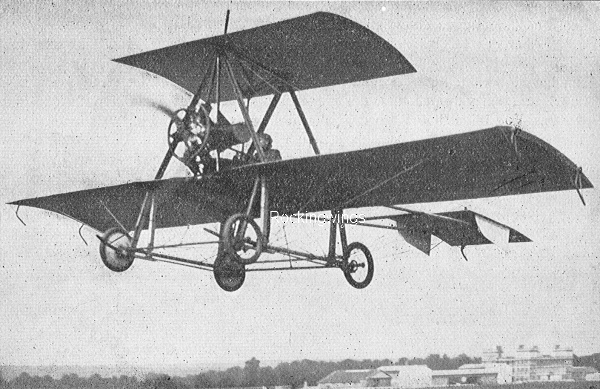
It represented a more professional approach to Watson's aeroplane building, being of considerably smarter appearance than his earlier efforts. It was sturdier, the proliferation of bracing wires were testimony to this. Constructed of welded steel tubing as opposed to bamboo in his earlier aeroplanes, one source claims the machine incorporated duralumin into its structure. Its wings were of conventional design; the bracing struts were fitted with streamlined aerofoil shaped fairings, made from aluminium or wood and covered in fabric. Streamlining extended to the wheels as well, with each hub being fabric covered.
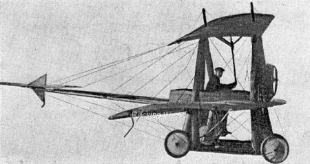
A retouched image of the No.3 that appeared in Flight in May 1914, but without the background blanked in. Note the difference in tail surfaces between this and the image at the head of the page. via Author
Structurally, the No.3 was simpler, the multitude of bracing wires taking the strain. Its wide-track four-wheel undercarriage chassis comprised a much neater and more robust vertically mounted strut arrangement, with small skids fitted inboard of the wheels that protruded ahead of them by a small margin only.
The 'A' frame cabane supports for the rocking wing commenced at the point on the top surface of the main wing where the undercarriage struts met the wing underside and sloped inward toward the rocking wing above the main wing. This was controlled by Watson's patented single interlinked elevator and rocking wing lever, which was attached to the upper wing's underside.
Camber on the wings was gentler on the No.3, in profile its trailing edge sloping away to a point considerably lower than the leading edge. Based on his experiences with a monoplane elevator on the No.2, the No.3 followed suit, although the tailplane was attached to the aircraft centre section by two single horizontal spars, which were heavily wire braced. As with the No.2 in its final form, there was no vertical tail surface except a triangular fillet above and below the elevator with their leading edge forming the upright for the tail skid. Skids were also fitted to the main wingtips.
The No.3's pilot was perched in the usual place in the one-piece main wing centre section, but he was afforded an element of protection from the slipstream with the provision of a wickerwork oval cockpit nacelle that started behind the engine and flared out to its widest point, where the pilot sat, tapering back to a point overhanging the rear of the wing trailing edge.
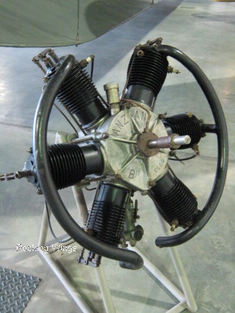
A six cylinder 45 hp Anzani on display at the RAF Museum at Hendon of the same type as fitted to Watson's third aeroplane. Grant Newman
Although the pilot's legs dangled below the wing, stirrups were provided for his feet. It is unlikely movement of these instigated any control input. The six-cylinder Anzani radial engine was mounted between two uprights inboard of the front cabanes that were angled inwards to the centreline of the rocking wing. Placed slightly above the wing leading edge, the engine sat directly in the pilot's line of sight, no doubt showering him with lubricating oil and exhaust fumes, as engines of open-cockpit aeroplanes of the period had a tendency to do.
Overall, the No.3 was significantly bigger than its predecessors; the tips of the bracing struts on top of the rocking wing stood at least another six feet above the top of the No.2's. Its wingspan was nearly 30 feet, with an overall length of 20 feet. The wide-track wheels were about eight feet apart. This increase in physical size over Watson's earlier aircraft was probably brought about by the use of metals in its construction; it also shows a greater confidence in his own ideas that was not present until he had achieved a certain competence in handling his designs in flight in the No.2.
To power his big No.3, Watson approached another British manufacturer of a French engine, The British Anzani Engine Company of Scrubbs Lane, Willesden, London. By 1913 when the No.3 was completed, British Anzani offered a choice of up to seven different types of engine, all with differing power outputs and cylinder arrangements.
Watson settled on a six-cylinder two-row radial costing £300, the first of its kind produced. Comprising two three-cylinder fan engines with their cylinders at 120° apart and rotated 60° to give each cylinder equal cooling, the Anzani radial's cast-iron cylinders were 90 by 120 mm. Weighing 189 lbs, it had an advertised power rating of 45 hp at 1,300 rpm.
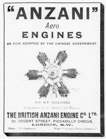
An advertisement in a contemporary aviation publication on the Anzani fitted to Watson's No.3 produced by the British Anzani Engine Company. The byline about the Chinese government refers to their purchase of Caudron G.3s built by British Caudron and powered by British Anzanis of the same type as in the advert. via the National Museums of Scotland
Photographs exist that show modifications undertaken to the No.3. Most noticeable are two prominent ellipsoidal vertical tails fitted to the elevator, which protruded above and below it; these were probably fitted because of the lack of a side surface component at the aircraft's rear. There was little vertical surface on all Watson's aeroplanes; he probably found that there was a degree of induced roll when the aircraft commenced a turn, something that he was keen to avoid.
Images published in foreign magazines also show the absence of fabric covers on the wheel hubs. These modifications were probably made during the time when the No.3 was entered into the Concours de La Sécurité en Aéroplanes at Buc, France in 1914; the unusual appearance of the No.3 warranted inclusion in both the German Flugsport and French L'Aerophile periodicals.
In March 1915, during an interview with a Flight magazine reporter, Watson mentioned in passing that he had fitted floats to the No.3. It is most likely that they were floatation devices that provided buoyancy in the event of the aircraft ditching during over-water flights. Watson said that he intended on carrying out further experiments with the No.3 after the end of the war, since he had applied for a commission with the Royal Naval Air Service.
According to James Manson, Watson's mechanic and sometimes pilot of the No.3, it was broken up around the time of the outbreak of war in 1914; it is likely that it had outlived its usefulness as an experimental machine.
Next, read about the Concours de La Sécurité en Aéroplanes competition here